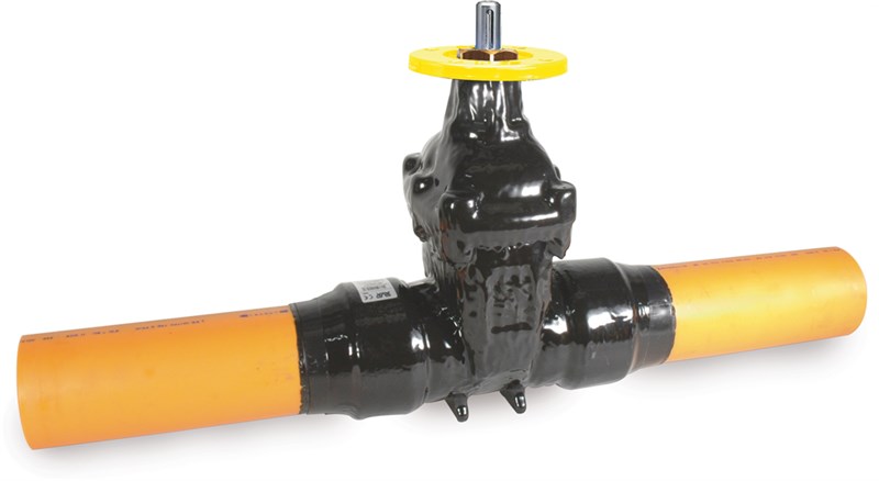
AVK GATE VALVE, PE PIPE ENDS, PN10
SDR11 PE100/PE100-RC pipe ends, ISO top flange, external PUR, replaceable stem sealing, NBR, DN80-300

Contact
Idriz Rahmanovic
Product Manager, Gas supply
Gate valve with PE pipes acc. to EN 1555-2 - PE 100 PN 10 SDR 11 pipes for gas -10°C to +20°C. Note: The maximum working temperature is set according to the ISO9080 lifetime requirements for PE pipes, and is therefore not the max. temperature for the valve.
AVK gate valves are designed with built-in safety in every detail and with full traceability of vital valve components. The wedge is fully vulcanized with AVK’s own oil and gas resistant NBR rubber compound. It features an outstanding durability due to the ability of the rubber to regain its original shape, the double bonding vulcanization process and the sturdy wedge design. The triple safety stem sealing system replaceable under pressure, the high strength stem and the thorough corrosion protection safeguard the unmatched reliability.
| Variant 36/78-010 | |
|---|---|
| Connection: | PE Pipe Ends |
| Material: | Ductile Iron |
| DN: | DN80 - DN300 |
| Closing direction: | Clockwise to Close |
Features
- Fixed, integral wedge nut prevents vibration and ensures durability
- Fully vulcanized wedge with guide rails and integrated wedge shoes
- Stainless steel stem with wedge stop and rolled threads for high strength
- Full circle thrust collar provides fixation of the stem and low free running torques
- Triple safety stem sealing with an NBR wiper ring and four NBR O-rings in a stem seal nut of dezincification resistant brass replaceable under pressure. A rubber manchette is the main seal to the flow.
- Round NBR bonnet gasket fixed in a recess
- Countersunk and sealed stainless steel bonnet bolts encircled by the bonnet gasket
- Full bore
- Low operating torque
- Fusion bonded epoxy coating in compliance with DIN 3476 part 1 and EN 14901, PUR according to EN 10290 type 2, class B for extra cathodic protection externally
- A standard PE pipe is pressed onto the grooved valve end, locked with a steel ring and sealed with a plastic shrink hose. The boltless, full bore PE end connection is fully tensile resistant and designed to meet all the criteria specified in DVGW G5600-1. The PE pipe end enables direct welding into PE pipes resulting in a fast and secure assembly.
Note: For higher working temperatures expect a reduction of the PE pipe’s lifetime. Please refer to the local pipe manufacturer for further information.
Downloads
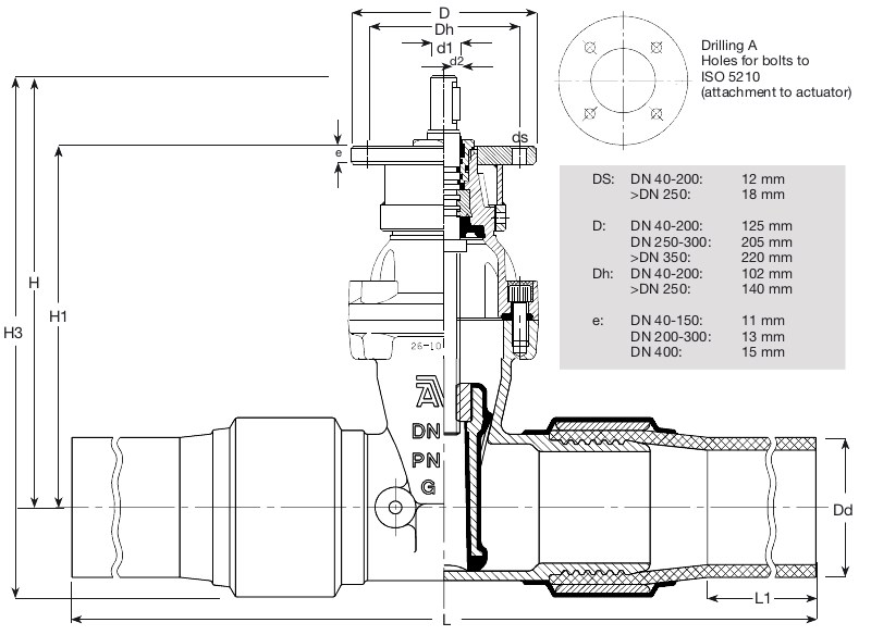
Reference nos. and dimensions:
| AVK ref. no. | DN mm |
Dd mm |
L (± tol) mm |
L1 mm |
H mm |
H1 mm |
H3 mm |
D1 mm |
D2 mm |
Actuator Flange |
Theoretical weight/kg |
|---|---|---|---|---|---|---|---|---|---|---|---|
| 36-090-78-701 | 80 | 90 | 900 (20) | 255 | 351 | 298 | 351 | 20 | 6 | F10 | 20 |
| 36-110-78-701 | 100 | 110 | 860 (20) | 265 | 334 | 276 | 401 | 20 | 6 | F10 | 27 |
| 36-125-78-701 | 125 | 125 | 890 (20) | 300 | 376 | 325 | 452 | 20 | 6 | F10 | 39 |
| 36-160-78-701 | 150 | 160 | 1070 20) | 265 | 448 | 376 | 545 | 20 | 6 | F10 | 52 |
| 36-200-78-701 | 200 | 200 | 1100 (20) | 300 | 562 | 472 | 677 | 20 | 6 | F10 | 88 |
| 36-225-78-701 | 200 | 225 | 1100 (20) | 265 | 562 | 472 | 696 | 20 | 6 | F10 | 91 |
| 36-250-78-701 | 250 | 250 | 1280 (30) | 270 | 664 | 555 | 810 | 30 | 8 | F14 | 118 |
| 36-280-78-701 | 250 | 280 | 1360 (30) | 365 | 664 | 555 | 823 | 30 | 8 | F14 | 126 |
| 36-315-78-701 | 300 | 315 | 1420 (30) | 265 | 740 | 630 | 924 | 30 | 8 | F14 | 140 |
Components
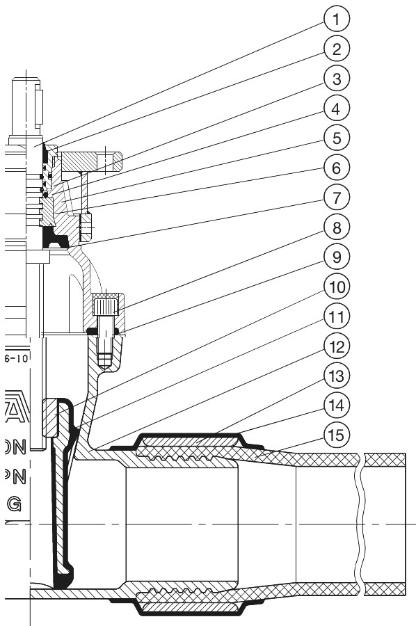
| 1. | Stem | Stainless steel |
| 2. | Wiper ring | NBR rubber |
| 3. | Stem seal nut | Dezincification resistant brass |
| 4. | O-ring | NBR rubber |
| 5. | Bonnet | Ductile iron GJS-500-7 (GGG-50) |
| 6. | Thrust collar | Dezincification resistant brass |
| 7. | Manchette | NBR rubber |
| 8. | Bonnet bolt | Stainless steel A2 |
| 9. | Bonnet gasket | NBR rubber |
| 10. | Wedge nut | Dezincification resistant brass |
| 11. | Wedge | Ductile iron, NBR encapsulated |
| 12. | Body | Ductile iron GJS-500-7 (GGG-50) |
| 13. | Sleeve | Carbon steel |
| 14. | Shrink hose | Plastic |
| 15. | Pipe | PE |
Test/Approvals
- Hydraulic test to DIN 3230-5, PG 3 and EN 13774, Hydraulic test to DIN 3230-5, PG 3 and EN 13774
- Seat: 1.1 X PN and 0.5 with air (in bar). Body: 1.5 X PN with water, 1.1 X PN and 0.5 with air (in bar)
- Approved according to DIN-DVGW Certificate NG-4313BO0281
- Approved according to DVGW EC Certificate CE-0085BO0317
Standards
- Designed according to EN 13774