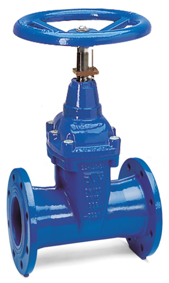
AVK GATE VALVE, FLANGED, PN10/16
EN 558-2 S.15/DIN F5, position indicator, NBR, DN40-400

Contact
AVK International A/S
Bizonvej 1, Skovby, 8464 Galten, Denmark
Flanged gate valve EN 558-2 S.15/DIN F5, with position indicator. For water and neutral liquids to max. 70° C
AVK gate valves are designed with built-in safety in every detail. The wedge is fully vulcanized with AVK’s own oil and gas resistant NBR rubber compound. It features an outstanding durability due to the ability of the rubber to regain its original shape, the double bonding vulcanization process and the sturdy wedge design. The triple safety stem sealing system, the high strength stem and the thorough corrosion protection safeguard the unmatched reliability
| Variant 02/66-006 | |
|---|---|
| Connection: | Flanged |
| Material: | Ductile Iron |
| DN: | DN40 - DN400 |
| PN: | PN16 |
| Closing direction: | Clockwise to Close |
Features
- Fixed, integral wedge nut prevents vibration and ensures durability
- Wedge fully vulcanized with NBR rubber and equipped with wedge shoes to provide smooth operation
- Wedge and body guide rails ensure stable operation
- Stainless steel stem with wedge stop and rolled threads for high strength
- Full circle thrust collar provides fixation of the stem and low free running torques
- Triple safety stem sealing with an NBR wiper ring, a polyamide bearing with four NBR O-rings, and an NBR rubber manchette
- Round NBR bonnet gasket fixed in a recess
- Countersunk and sealed stainless steel bonnet bolts encircled by the bonnet gasket
- Full bore
- Low operating torque
- Fusion bonded epoxy coating in compliance with DIN 3476 part 1 and EN 14901, GSK approved
- Position indicator on the stem for visual or remote read-out of the valve position
Downloads
| AVK_Gate valves_animation_2022.mp4 |
Reference nos. and dimensions:
| AVK ref. no. | DN mm |
Flange drilling |
L mm |
D mm |
H mm |
H3 mm |
W mm |
Theoretical weight/kg |
|---|---|---|---|---|---|---|---|---|
| 02-040-66-013 | 40 | PN10/16 | 240 | 180 | 329 | 404 | 150 | 14 |
| 02-050-66-013 | 50 | PN10/16 | 250 | 180 | 329 | 404 | 165 | 14 |
| 02-065-66-013 | 65 | PN10/16 | 270 | 225 | 355 | 428 | 185 | 15 |
| 02-080-66-013 | 80 | PN10/16 | 280 | 225 | 382 | 482 | 200 | 19 |
| 02-100-66-013 | 100 | PN10/16 | 300 | 280 | 414 | 524 | 220 | 25 |
| 02-125-66-013 | 125 | PN10/16 | 325 | 320 | 461 | 586 | 250 | 33 |
| 02-150-66-013 | 150 | PN10/16 | 350 | 320 | 540 | 683 | 285 | 54 |
| 02-200-66-003 | 200 | PN10 | 400 | 360 | 688 | 858 | 340 | 76 |
| 02-200-66-013 | 200 | PN16 | 400 | 360 | 688 | 858 | 340 | 76 |
| 02-250-66-003 | 250 | PN10 | 450 | 500 | 780 | 980 | 422 | 121 |
| 02-250-66-013 | 250 | PN16 | 450 | 500 | 780 | 980 | 422 | 121 |
| 02-300-66-013 | 300 | PN16 | 500 | 500 | 855 | 1083 | 455 | 171 |
| 02-400-66-013 | 400 | PN16 | 600 | 640 | 960 | 1250 | 580 | 360 |
Components
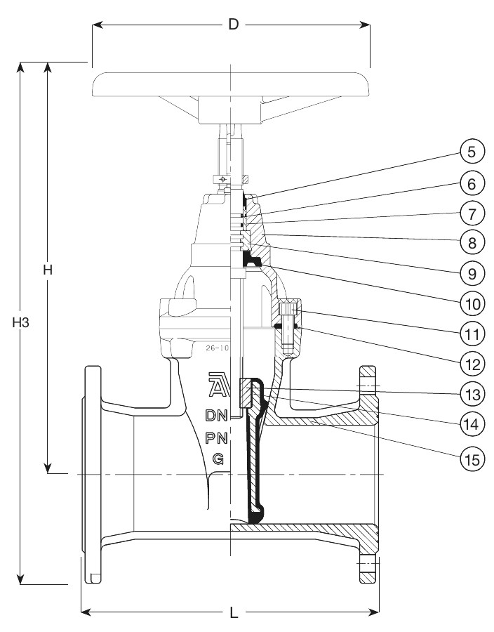
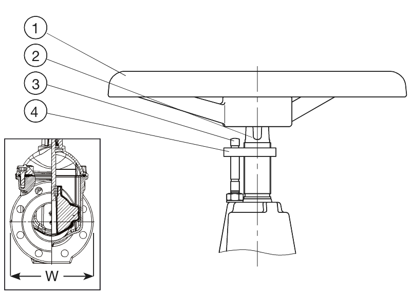
| 1. | Handwheel | Cast iron GJL-250 (GG-25) |
| 2. | Stem | Stainless steel 1.4104 (430F) |
| 3. | Pin | Stainless steel |
| 4. | Indicator nut | Dezincification resistant brass |
| 5. | Wiper ring | NBR rubber |
| 6. | O-ring | NBR rubber |
| 7. | Bearing | Polyamide |
| 8. | Bonnet | Ductile iron GJS-500-7 (GGG-50) |
| 9. | Thrust collar | Brass, DZR CW602N |
| 10. | Manchette | NBR rubber |
| 11. | Bonnet bolt | Stainless steel A2, sealed with hot melt |
| 12. | Bonnet gasket | NBR rubber |
| 13. | Wedge nut | Brass, DZR CW626N |
| 14. | Wedge | Ductile iron, NBR encapsulated |
| 15. | Body | Ductile iron GJS-500-7 (GGG-50) |
Test/Approvals
- Seat: 1.1 x PN (in bar), Body: 1.5 x PN (in bar). Operation torque test
- Approved for wastewater
Standards
- Designed according to EN 1074 part 1 & 2
- Face-to-face dimension according to EN 558 Table 2 Basic Series 15
- Standard flange drilling to EN1092-2 (ISO 7005-2), PN10/16
Use with this product
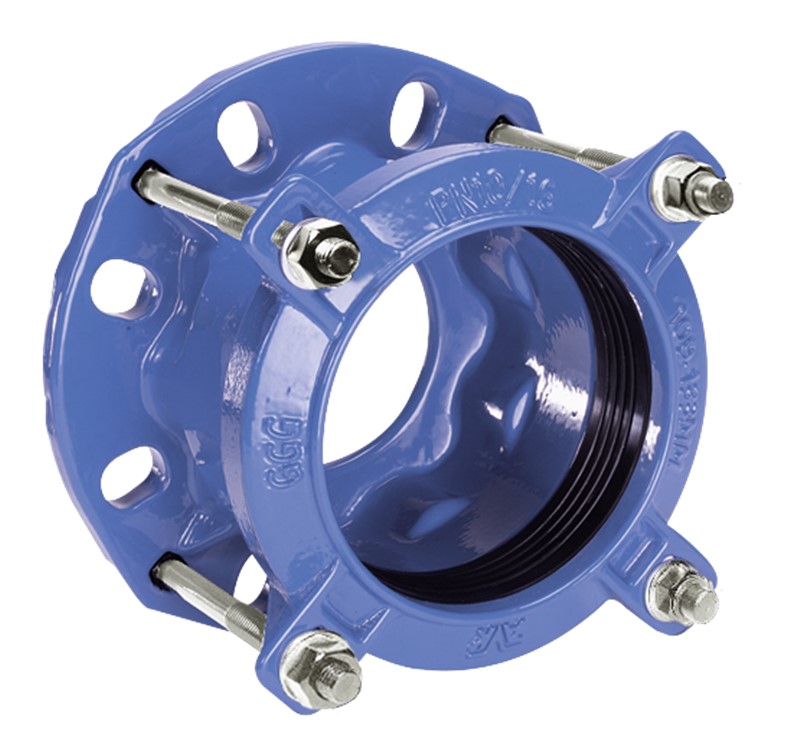
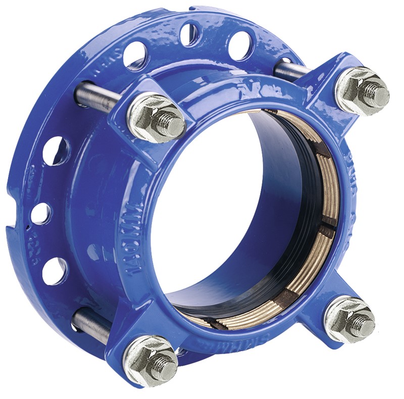
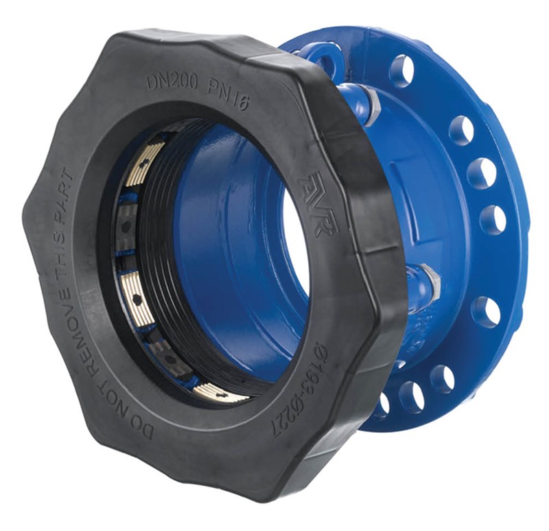
AVK SUPA® FLANGE ADAPTOR, PN16
Universal, A2 bolt/A4 nut deltaseal, NF approved EPDM sealing, DN40-400